Morphological Operations
When processing images, the raw images may contain more information than what is needed, or in other cases, less information then what is needed. An image may be noisy, containing to many random artifacts, or perhaps it may be too sharp that some data is lost on the edges in the image. To deal with these problems, we make use of morphological operators.
The activity we will be performing centers around the morphological operations of erosion and dilation. Both operate by comparing a pixel and the pixels surrounding it to a structuring element. Erosion would remove pixels and dilation would add pixels depending on the overlap of the image and the structuring element.
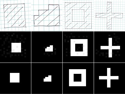
We focus on binary erosion and dilation for this activity. We create 4 different binary images, a 5×5 square, a triangle with a base of 4 units and a height of 3 units, a 10×10 hollow square having an edge 2 units thick, and finally a cross with leg length of 5 units and 1 unit wide.
For each of these images, we perform both dilation and erosion with the following structuring elements.
However, before we begin with processing these images using a computer, we first attempt to predict the outcome by drawing all the images.
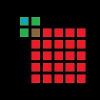
Having drawn the initial image, we overlap the structuring element. Take note that for a structuring element, there is a point in question which will change in value depending on the result of the morphological operation. In the case of a square structuring element, we can designate the upper-left corner as an anchoring point. When performing dilation, as long as part of the structuring element overlaps with the binary image, the pixel in question will become one. When performing erosion, the pixel in question will be zero unless the entire structuring element is within the binary image.
In the example above, the green structuring element overlaps with the red image. If the process being performed is dilation, the blue pixel in question will become one (considering a binary operation). However, if the process being operation being performed is erosion, since the whole of the structuring element is not within the image, the blue pixel in question will remain zero.
This process is repeated for every point until the structuring element has scanned the entire image. Hand drawn predictions were made for all images for all structuring elements.
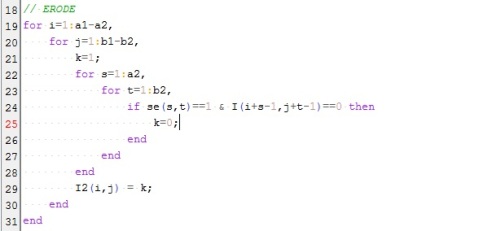
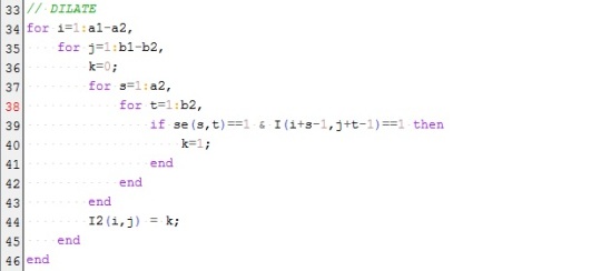
Now that we have an initial prediction of the results, we can now process the images using a computer. Since the SIVP toolbox in scilab does not have functions for morphological operations, two independent results were taken to validate the data. One using Matlab, and one using a code that I wrote using some SIVP functions.
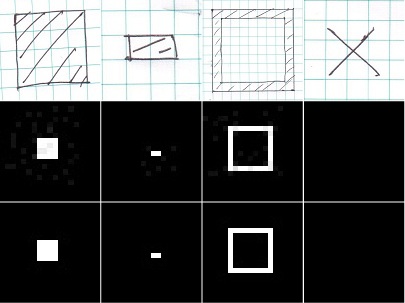
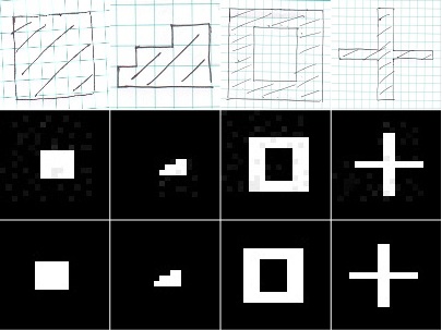
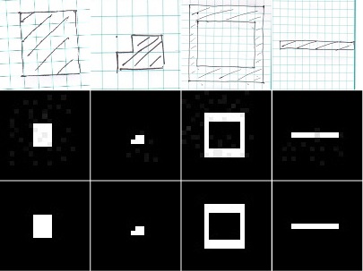
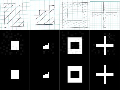
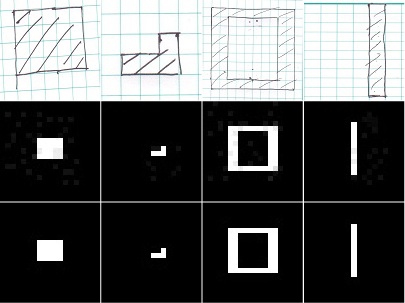
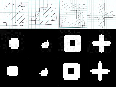
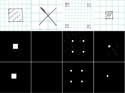
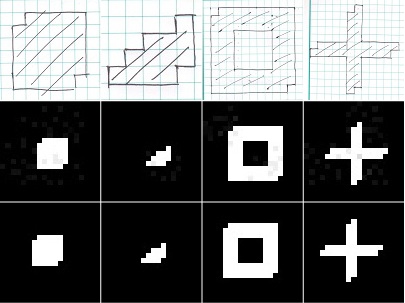
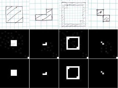
Below are the hand drawn, Matlab, and Scilab results for all images for each structuring element.
Above are the results for dilation with a 2×2 ones structuring element. Each dimension was enlarged by one unit as a result of the operation.
Consequently, the same structuring element reduces the size of each dimension by one unit when erosion is applied.
Reducing the structuring element to a 2×1 ones matrix, dilation elongates the image in the horizontal direction.
Conversely. performing erosion with the same structuring element reduces the horizontal length of the image. Most evident in the cross image, all that remains is a horizontal bar.
Changing the orientation of the earlier structuring element into a 1×2 ones matrix, dilation stretches the image in the vertical direction.
Again, the opposite happens when applying erosion, reducing the vertical components of the image by 1 unit.
A cross-shaped structuring element was used in the above results. One can easily replicate the dilation results for this by simply scanning the points of the image and adding a one above, to the left, right, and below each pixel.
The results for erosion on the other hand, show how many pixels have adjacent ones in all 4 directions.
A diagonal structuring element used in dilation results in an image as if the original image was displaced diagonally and overlaid on each other.
On the other hand, performing erosion with the same structuring element identifies how many pixels can be found diagonal to each other.
The results for Matlab and for my personal code appear to be similar and match the expected hand drawn results. One noticeable difference between Matlab and my personal code is that the results seem to shift for certain images. We can attribute this to a different point being used as the pixel-in-question in the structuring element. Another thing to note is that the Matlab code used was not specified for binary morphological operations, therefore, one can perceive certain gray spots outisde the expected image.
There are some considerations that need to be taken when using morphological operations. First, it is ideal that the image being processed shold have a large enough background of zero information such that the structuring element can fit within the zero background without overlapping the image. The minimum allowed would be an overlap of the edges. A larger overlap would reduce the scanning of the structuring element and therefore reduce the information obtained.
Another consideration, at least when applying my personal code, is the size of the image. Since my code uses 4 nested for loops, given a large image, the time needed to process the image would increase drastically, making it inefficient in such cases.
For this activity, I will be giving myself a 12/10 since the objectives of the activity were met and I was able to explain the considerations one would need to take into account when performing these operations. The original code written, also shows a decent amount of comprehension on my part.


